
Securing Self-Hosted Resources With Cloudflare - Part 2
Welcome to Part 2, Electric Boogaloo! Part 2 of anything must be called Electric Boogaloo. I don’t make the rules, that’s just the way it is.
In Part 1, we covered the following.
- Setting up a reverse proxy.
- Setting up your CloudFlare DNS and SSL/TLS certificates.
- Setting up your virtual hosts and enabling SSL/TLS on each virtual host.
In this part, we will cover the following.
- Enabling SSH.
- Setting up dynamic DNS (DDNS).
- Setting up port forwarding.
- Setting up firewall rules to restrict all inbound traffic to CloudFlare.
All examples will be Ubiquiti specific but the concepts are the same for all firewall vendors.
1. Enabling SSH
Before we can make changes to how the Ubiquiti equipment functions, we will need to enable SSH. To do this, use a web browser and log into your Unifi console and make sure you are in the UnifiOS app. From there, you can select Console Settings and click the checkbox next to SSH. UnifiOS will prompt you for a password. Enter a secure password.
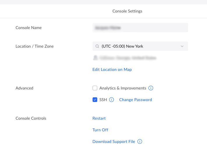
That’s it! You have enabled SSH on your Ubiquiti device. This process works the same for all current Unifi consoles, such as Cloud Key Gen 2, UDM, UDM Pro, and UDM SE. If you want to be extra secure, you can add ssh key authentication to the console, but that is an article for another occasion.
2. Dynamic DNS (DDNS)
In Part 1, you manually set the IP address of your root A record in DNS. This works only as long as your IP does not change. So we need to set up a process to automatically update our root A record every time our modem gets a new IP address.
First, we will need to create an API token. This is a long string of characters that is like a secure password for an application to use with your CloudFlare account. Log back into your CloudFlare dashboard. Click on the little person icon at the top right. From that menu select My Profile. Now select {} API Tokens from the menu on the left. Now you are going to click the “Create Token” button. This will take you to a new screen, where you can select the “Edit zone DNS” template. This will guide you through creating a token with permission to only edit your DNS zone records. The default options are all fine, except for of the Zone Resources section. In that section, you should have Include, Specific Zone, and your zone (or domain name) selected. Make sure to save the token presented at the end of the wizard. CloudFlare has a very good guide on this process.
Out of the box Ubiquiti uses inadyn. However, the GUI does not support CloudFlare at this time. I did attempt to manually set it up in Ubiquiti’s MongoDB but it only returned errors from CloudFlare. So, we’ll set it up manually. Begin by connecting to your Unifi console with SSH.
ssh root@unifi
Once connected, you will need to edit /etc/inadyn.conf. Ubiquiti has VIM by default so that is what we will use.
vim /etc/inadyn.conf
If you are not familiar with VIM, then here are the basics. By default, you are in COMMAND mode. In COMMAND mode you can issue commands and move around the file but you cannot edit. To start editing press the “i” key on your keyboard, this will place you in INSERT mode. Now you can still move around using the arrow keys and you can edit. Change the values in the config file to the following.
|
|
Obviously, replace example.com with your domain name and YOUR_CLOUDFLARE_API_KEY with your actual API key. If you are updating a subdomain like lab.example.com, then change hostname to the subdomain you are updating. Go ahead and save the file by hitting “Esc” on your keyboard, this will take you out of INSERT mode and back into COMMAND mode. Now type “:wq”. This will (w)rite and (q)uit the file. While the purpose of some variable names is obvious, ttl and proxied may not be. The ttl variable tells inadyn to use a secure connection and excepts values of 0 (false) and 1 (true). The variable proxied accepts true or false values and tells CloudFlare to set the Proxied toggle in your DNS records to on or off.
Now we need to activate inadyn in systemd. There are two simple commands, the first will enable inadyn, and the second will start inadyn.
systemctl enable inadyn
systemctl start inadyn
Once both of those commands have been executed, your DNS records will be updated if they do not reflect your current IP address. You can check the status of inadyn at any time with the following command.
systemctl status inadyn
3. Port Forwarding
In Part 1, we set up three hosts in the reverse proxy Home Assistant, Emby, and Vault Warden. In those examples, I chose to put Home Assistant and Emby on port 8443, and Vault Warden on port 443. This was an arbitrary decision and they could all sit on the same port, but since that was the prior example we will continue with that port scheme.
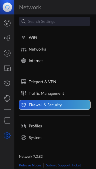
Back in the Unifi Networking app, click on the gear icon in the menu to the left and select Firewall & Security from the sub-menu.
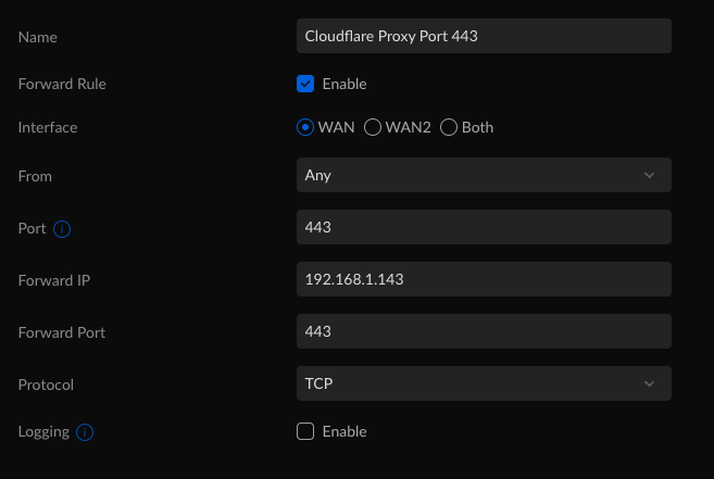
You will repeat this step for each service that you are presenting to the web. The “Forward Port” and “Port” values will differ with each service. So, while the above example is for Vault Warden hosted on port 443, Emby, and Home Assistant the “Forward Port” will be 8443, and the “Port” will be 8443. This is assuming you used the NGINX examples from part one.
4. Firewall Rules
The final part of this process is to restrict the traffic so that we only allow traffic from CloudFlare. While this is not a required step, it does increase security by only allowing traffic forwarded via CloudFlare. This cuts down on bots that are probing for networks to attack. Additionally, should your home server come under attack, you can now implement CloudFlare’s mitigation tools.
Now, you’d probably think “I’ll just go and create a rule that only accepts traffic from the CloudFlare Proxy servers” and you’d be correct, except for one detail. Ubiquiti will not allow you to enter multiple addresses or multiple ports as sources or destinations. Instead, Ubiquiti requires that you define Port or IP groups. You can do this while creating the firewall rule but I’m going to show you how to do it through the Profiles page. Which is where you’d go to manage those profiles.
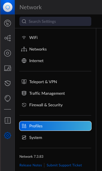
Just, like in the forwarding portion of this post, you will need to go to the gear icon in the Unifi Networking app. From there, you will click on Profiles near the bottom of the menu on the left.
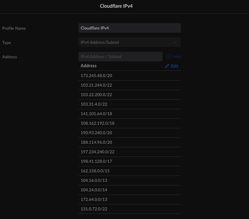
At this point, we will need to create two groups, one for IP addresses and one for ports. First, you will need to scroll to the bottom of the Profiles page and click “Create New Port/IP Group”. Give the group a name, for example, “CloudFlare IPv4”. Change the type to “IPv4 Address/Subnet”. In the “Address” field add the CloudFlare IPv4 subnets. You can always get an up-to-date list from CloudFlare. Once you have completed that, you will have a list similar to the one below.
Repeat this process for IPv6, just make sure to select a type of “IPv6 Address/Subnet” and change the name to something like “CloudFlare IPv6”.
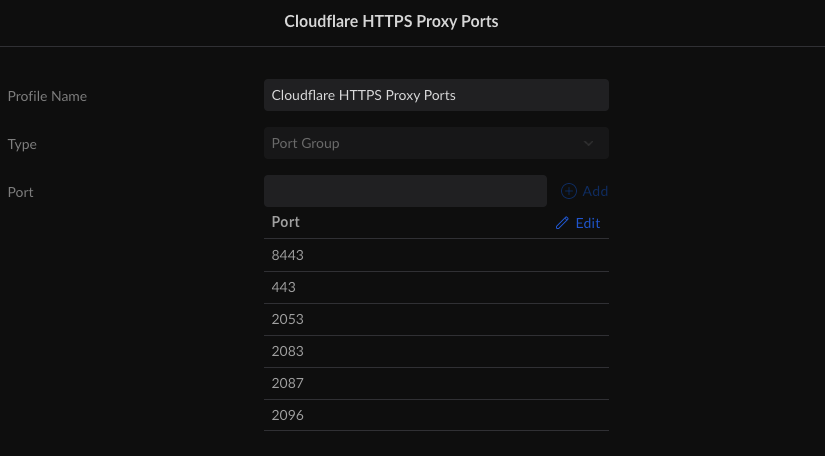
Now we just need to create the Port Group. This is the exact same process as creating IP groups, except the type is “Port Group”. In this example, we are only concerned with HTTPS proxy ports, so we will only create a group called “CloudFlare HTTPS Proxy Ports” and only use ports 443, 2053, 2083, 2087, 2096, and 8443. Technically, you should only list the ports you are going to use, but since CloudFlare only allows specific ports, I’m including them all here for completeness. In the end, your “Port Group” should look like this or contain only selected ports from the list.
We are now ready to configure our firewall rule. Once again we will be in the Firewall & Security tab on your UDM-Pro or UDM-SE. Here we will create two rules, one that allows traffic from CloudFlare on the authorized ports and one that drops all non-CloudFlare traffic on the authorized ports.
The first rule is the “Allow CloudFlare Proxy” rule. On the Firewalls & Security screen, you will click the “Create New Rule” button in the Firewall Rules section. When creating the rule, you will need to choose a type of rule. The types break down into six major types, Internet, Internet v6, LAN, LAN v6, Guest, and Guest v6; and three subtypes per major type In, Out, and Local.
- Internet is for all IPv4 traffic to and from the internet. Internet v6 is the same as Internet but for IPv6 traffic.
- LAN is for all local area network IPv4 traffic. This is inclusive of all VLANs but excludes guest networks. LAN v6 is the same as LAN but for IPv6 traffic.
- Guest is for all IPv4 networks using the guest network profile. Guest v6 is the same as Guest but for IPv6.
That explains the major types but what about the subtypes? Well, they are even simpler.
- In is all traffic coming into a network and routed to a different network.
- Out is for all traffic going out of a network and routed to a different network.
- Local is for all traffic going to that specific network.
Now, I’m sure many are still a little confused about this but I think it will make more sense if we just set up our first rule and explain it along the way. So back to creating our allow rule for CloudFlare. Below is an image with all the options that we need to set.
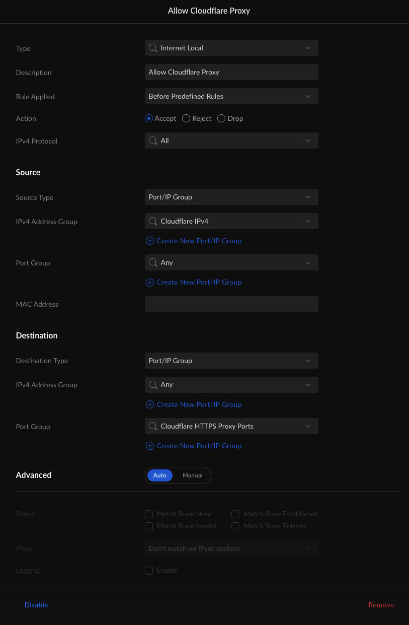
Some of this is kind of obvious. Source IPv4 Address Group is the CloudFlare IPv4 profile we created earlier. Destination Port Group is the group CloudFlare HTTPS port group we created earlier too.
Some of this is not so obvious. Why is the type Internet Local and not Internet In? Well, both would work and are technically correct (the best kind of correct), but one is more correct than the other. If you recall from our earlier setup, we are port forwarding traffic from the internet to our LAN, this is not routing. As a result, while both In and Local would work in this situation, Local is the more correct choice as the Internet connect interface is the final routed destination. What about Source Port Group? Why is it Any instead of our CloudFlare Proxy Ports? While services must listen on “well-known” or “advertised” ports to handle incoming requests, the outbound request does not need to be on a specific port and is usually a randomly selected high-numbered port. So the destination port might be 8443 but the source port could be 56729. Last one, why is Destination IPv4 Address Group set to any? Well if we had a static IP address, we could lock it down to just that address but we have a dynamic address. With dynamic addresses, we need to leave it as Any so the rule doesn’t break every time we get a new address.
The last rule is the block rule. Technically we don’t have to add this as the firewall has default rules that drop all traffic that is not explicitly permitted. However, when securing a service, it’s generally a good habit to create a matching block rule to catch anything that does not belong.
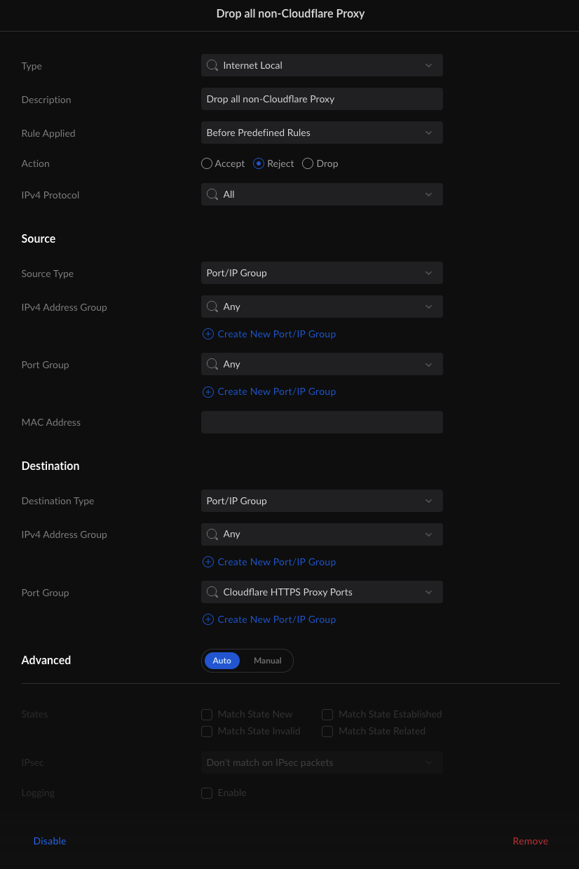
This rule looks very similar to the first rule, with only a few changes. The first is the Action Type. In the “allow” rule the Action Type is Allow but this one is Reject. Well, Allow allows traffic and Reject rejects traffic. What’s Drop do? Drop is like when you ask your SO to do something and they pretend not to hear you. The firewall does the same thing, it heard the traffic and then just “forgot” about it, as if nothing happened. What about the Source IPv4 Address Group? Why is it Any? Well, traffic is allowed, rejected, or dropped by the first rule that matches it. Since our Allow rule comes before this rule, CloudFlare traffic is already allowed in, this means that any non-CloudFlare traffic, going to our CloudFlare proxy ports is trapped by this rule. It’s worth noting, some firewalls have a negate operator, in those firewalls the rules would be identical except for the Action Type and the Source IPv4 Address Group. The Action Types would still be Accept and Reject (or Drop if you prefer) but the Source IPv4 Address Groups would CloudFlare IPv4 and NOT CloudFlare IPv4.
5. Conclusion
Wow, part 2 is a lot denser. Don’t feel bad if this is hard to understand. DNS, firewalls, IP traffic, and routing are all a bit more advanced concepts for most non-IT people.
If you get stuck or confused by any of this or you spot any errors, of which I am sure there are many. Hit me up on one of the social links to the left and I will do my best to make corrections and answer any questions you might have, within reason.