
Tronxy X5SA-500 Pro Bed Leveling
A while ago, I purchased a Tronxy X5SA-500 Pro large format printer. My intent was to print really large objects, like replacement panels for motorcycles, think Goldwing battery covers. What I could not have known is that this printer would become an engineering challenge and the bane of my existence…
When I first got the printer, I had the usual new toy excitement. I quickly assembled, leveled, and tested the printer. It did OK with the stock GCODE, but any new items I rendered quickly had issues. Over time I began to find lots of shortcomings with the printer.
Marlin
First up was the poorly implemented version of Marlin on the stock controller. I dug around in Marlin and figured out how to modify the source code and add support for the new, at the time, Chitu v9 board. I even contributed the changes, as poor as they were, to the Marlin source code, commit #22401. Better coders than I cleaned it up and made it part of the released code.
This was not too bad at first, but I kept running into strange behavior with the board and random glitches. So, I eventually swapped out the board with a Bigtree Tech Octopus v1. This fixed many of my glitch issues but every time I made one improvement, it lead to discovering another issue that was hidden by the unreliability of the printer.
The Hotend
The next big change was to eliminate the dual feed mixing hotend. When I purchased it, I was hoping to be able to swap back and forth between two different filaments with ease. Instead, I found that the stock hotend was a jam machine. Prints would start out OK, but about a quarter of the way through the hotend would develop clogs, and forget about switching to the second filament, that was just a non-starter. The end result was to replace the hotend with a E3D Volcano.
The new Volcano required a new mount and I did find someone had designed one for the printer. It didn’t quite match the mounting plate on my printer. This lead to my first really complex CAD model, a mount for the hotend. I figured if I was gonna go this far, I may as well upgrade the extruder, as I was having feed problems there too, and upgrade to direct drive. This made the hotend model more complex, and more of a learning experience in Fusion 360.
After many trials and errors, I got a working model. It’s not perfect, and has a few design flaws that will be fixed in future iterations but it works. Just as before, as the reliability of one component increase, a flaw with another one became more obvious. This latest flaw, was the root of several issues, and was visible all along, bed leveling.
The Bed Problem.
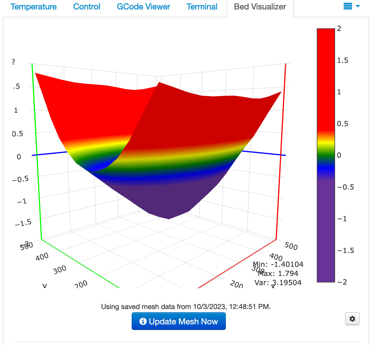
Now we are at the heart of this article. All along, I had a bed leveling issue. However, I fooled myself into thinking that bilinear bed leveling (ABL) could compensate for the problem. Usually, ABL works well, but is really not meant to handle big variations in the bed level. Add to that, the enormous bed and imprecision in the stock magnetic bed leveling sensor, and it becomes impossible to correct.
Crushinator’s taco bed.
So, at this point I had two issues to resolve. First being the imprecision of the bed level sensor, easily fixed by changing out to something I’ve used and trusted in the past, a BLTouch. And second, the taco shaped bed.
The second fix is a bit more complex. I needed a way to support the center of the bed, not interfere with any of the printers mechanisms, adjustable, and last easy to build. The easy to build part is because I did not want to dismantle the entire printer and I do not have any metal working capabilities. Good thing I have other 3D printers to print parts, and access to McMaster-Carr.
So, I began to design my parts a little different than I usually would. Normally, I’d draw out what I think the part should look like, print a sample, test fit, make adjustments, and repeat. This works but is slow and consumes lots of plastic. So, this time I decided to learn about components, joints, and parametric modeling. This is not a guide on those topics, as there are tons of YouTube videos explaining it better than I can. What I can tell you is this is a game changer for modeling. By modeling the physical objects, you can better model and test fit your part in software. Parametric modeling makes it so that instead of re-drawing sketches or re-extruding parts, you can define variables for all the important pieces. Need to change the diameter of a post, or reposition the space between holes, just change the variable value and watch the model reshape itself to match.
So, the part design ended up as a bracket that engages with the ball screw lift bearing and the predrilled holes on the sides of the lift bearing. Attached to the bracket is a standard 20mm extruded aluminum t-rail, in my case 29.25 inches. Please excuse the mess in some of the images.
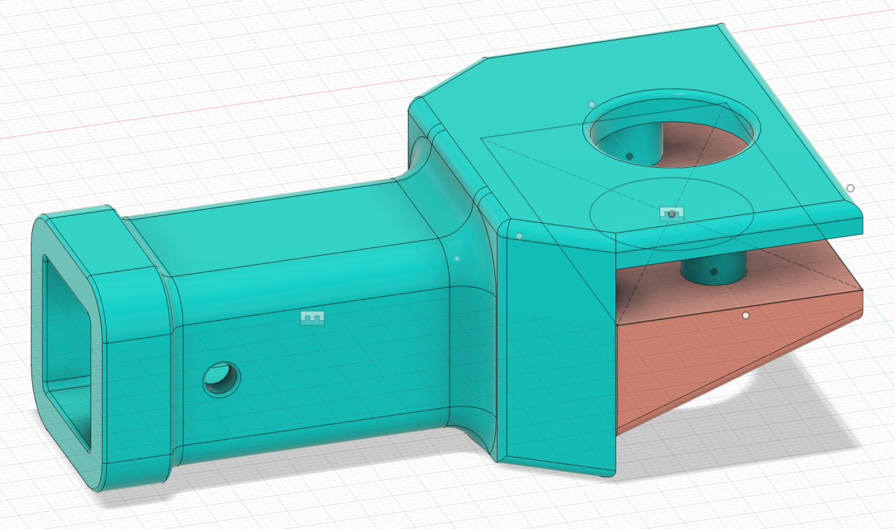 Model bracket top side view |
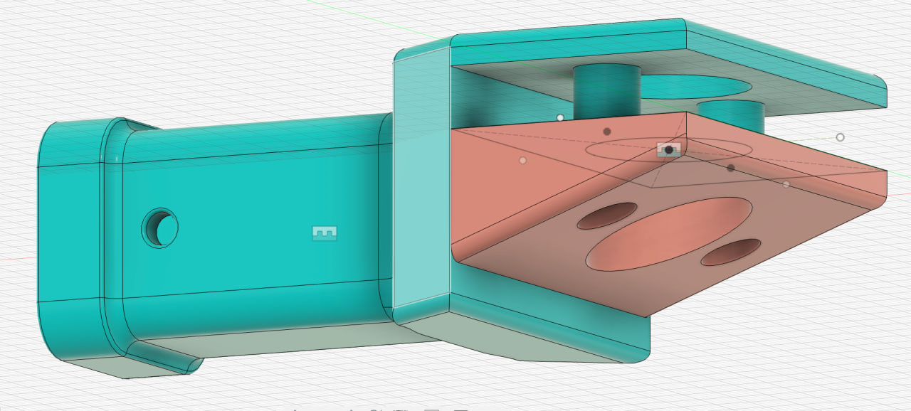 Model bracket bottom side view |
|
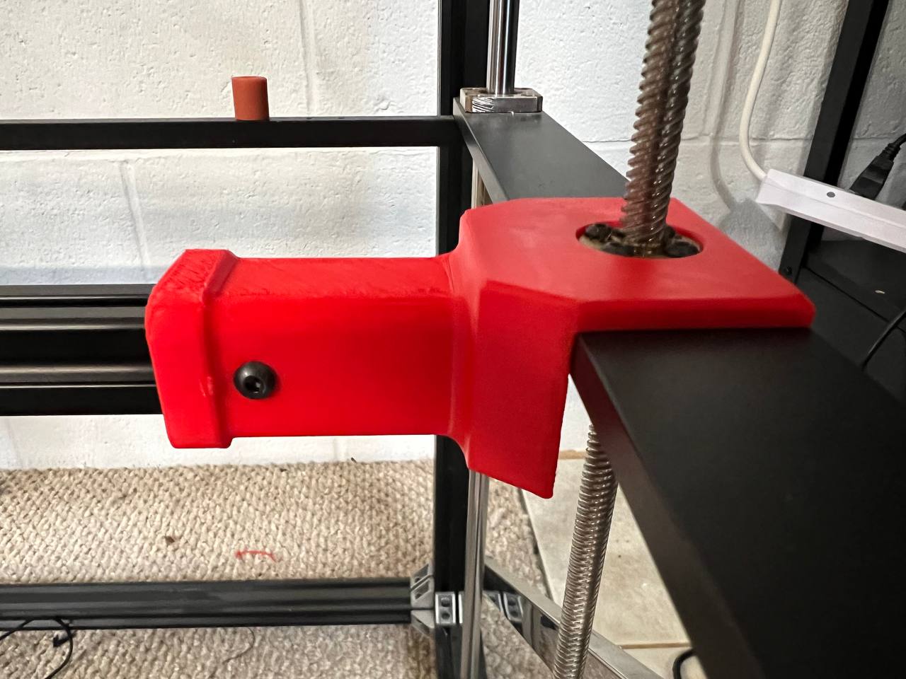 Printed support bracket |
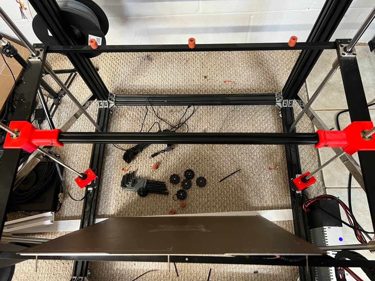 Top view of the support |
The red blocks resting on the z-axis steppers, is the clamps that screw into the bracket.
Not shown in the images are the screw holes, M3 screws, t-nuts, and pads. Basically, I drilled three holes into the t-rail. Placed an M3 screw in the holes and used t-nuts to hold the screws in place. On the top of each screw is a 3D printed pad that is used to lift the center of the bed.
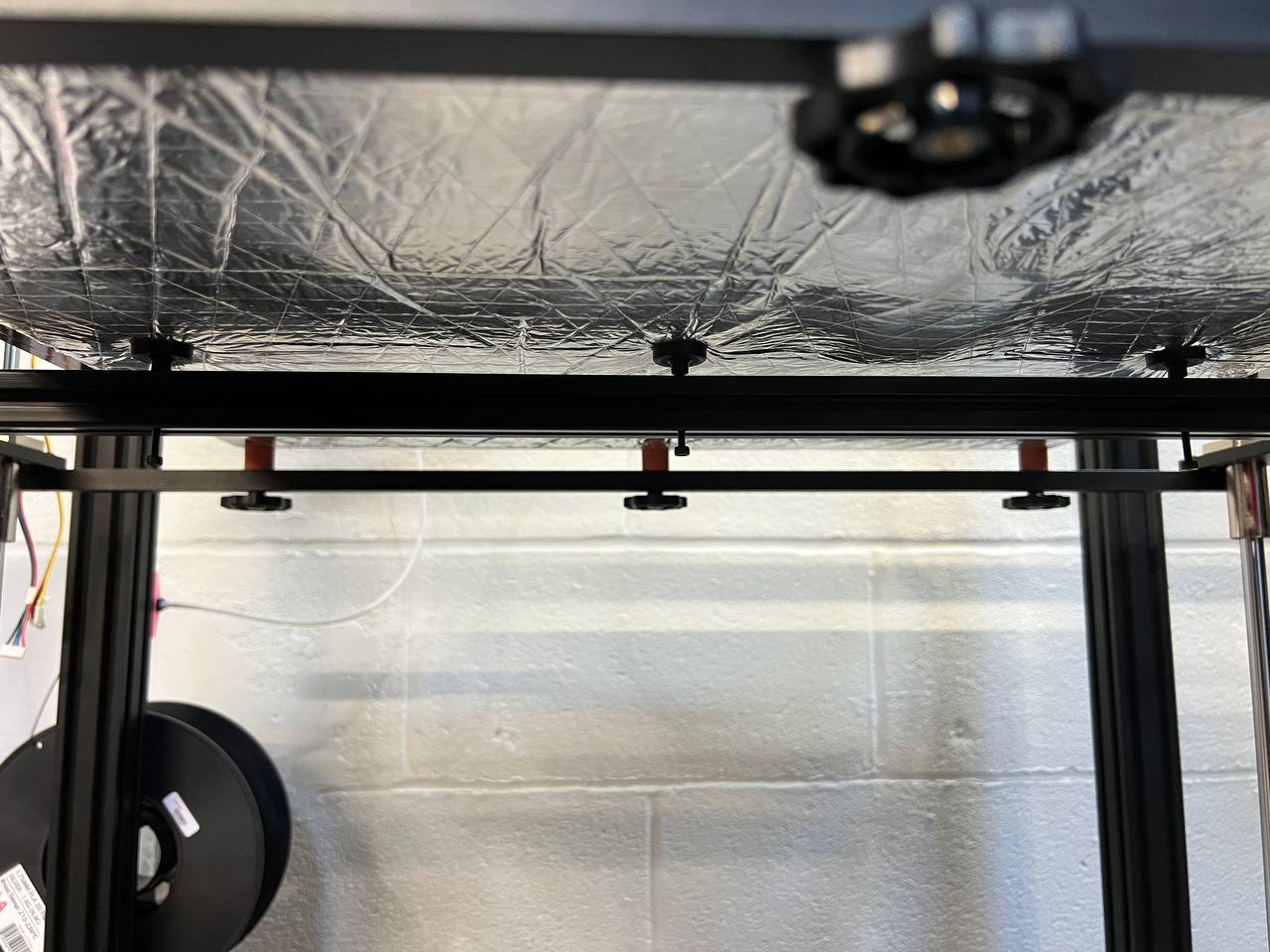
The assembled support rail.
Drumroll, please
Now, I can adjust the sag in the middle of the bed, still not perfect but much better than before.
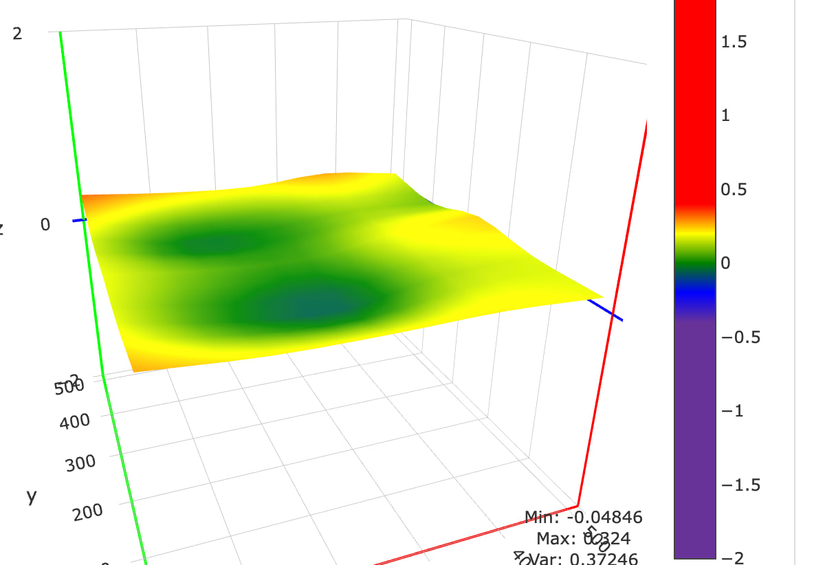
Crushinator’s “levelish” bed.
Yes, there are defects in the bed still. Unfortunately, the bed provided by Tronxy is too flimsy to hold it’s own weight, much less the weight of anything printed on it or any upgraded bed surfaces. If you are thinking of getting a large format printer, look at someone other than Tronxy. However, if you already have a Tronxy and need to fix the same bed issue, download the models at my Printables page.